Drag Racing with Jim Hand – Part 18: Pontiac Cranking System
- March 16th, 2010
- Posted in Jim Hand: Drag Racing . Technical Articles
- By D.A.P.A
- Write comment
A fairly common occurrence after a lot of miles, or after we rebuild our Pontiac engines, is poor operation of the cranking system. This column will discuss the separate parts of the cranking system, the function of each part, and some suggestions that may help improve your Pontiac’s cranking system.
The cranking system of a Pontiac V8 (and all similar GM vehicles) consists of:
1. Battery and two battery cables
2. Starter motor
3. Starter solenoid
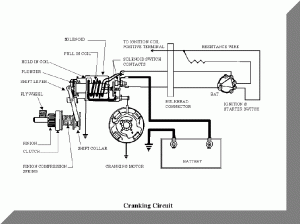
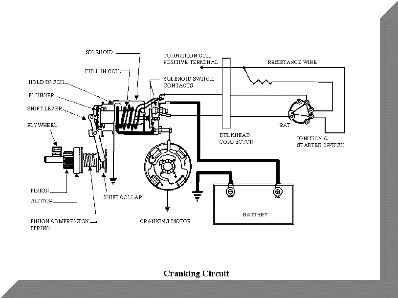
4. Electrical starter controls (See drawing for a typical starting system.)
Brief Theory of the Cranking system
The battery stores electrical energy in chemical form until it is needed by some part of the automotive electrical system. The energy is measured by stating the voltage and current rating of the battery. A rough analogy to electrical voltage is the pressure in a home water system. Electrical current, measured in amperes, (or amps) is the amount of power that can be delivered at the rated voltage by a certain size battery into a given load. Current can be thought of as somewhat similar to the amount of water that can be delivered at a stated pressure and through certain size pipes. As a normal vehicle battery is rated at 12.4 volts, and some quantity of amps, and load requiring more than the amp capacity of the battery will cause the voltage to drop below 12.4 volts. Current is determined by a combination of the voltage and the electrical resistance that the current has to pass through. Thus, if the resistance path (wiring, connections, switches, etc.) becomes higher resistance than originally designed, the currents passing through the loads (motors, solenoids, lamps, etc.) and the voltage at the loads, will be lower than needed and the loads will not operate as designed.
The negative battery cable connects the negative post of the battery to the engine. The engine is electrically connected to the frame and body via ground straps. This combination of engine, body, and frame provides a conductive path (called “ground”) from all devices on the vehicle that are connected to ground back to the battery negative post. The positive cable is connected from the positive post of the battery to the large + post on the solenoid. A smaller wire is also connected to the same point on the solenoid and conducts the 12V power to the remainder of the vehicle’s electrical system.
The starter motor is a very high current and powerful direct drive electric motor that rotates and turns the engine via the ring gear (flex plate), when the solenoid operates. The starter includes the starter drive gear that is equipped with an over-running clutch. The drive gear that is splined to the motor shaft and designed to slide on the shaft so it can be driven into mesh with the ring gear when the solenoid operates. The over-running clutch protects the starter from excessive speed when the engine fires.
The solenoid is an electrical relay that has two major functions when the ignition start circuit is activated. It drives the starter gear outward on the starter motor shaft in order to engage in the starter gear with the ring gear teeth. That movement almost simultaneously closes a high current switch (located within the solenoid) between the positive battery cable and the starter motor. A third minor function of some Pontiacs is to furnish a full 12V to the ignition coil during “start” (bypassing the ignition ballast resistance).
The starter/cranking controls include the “start” position of the ignition switch, the Neutral start switch on automatic equipped vehicles, and all of the wiring and connectors from the smaller positive wire on the solenoid + terminal, through the bulkhead (firewall), through the ignition switch, through the neutral start switch, back through the bulkhead, and finally to the “S” terminal on the solenoid.
Sequence of Operation
When we turn the ignition switch to “start”, the following events occur: (assuming a good battery and proper wiring).
- Power is switched to the “S” terminal on the solenoid causing the solenoid to operate. It requires 40 to 50 amps to operate the solenoid.
- The solenoid drives the starter gear out and against the ring gear and closes the high current switch between the battery positive post and the starter motor windings.
- The starter motor begins to rotate causing the drive gear to rotate and slide into mesh with the ring gear. (if it was not initially engaged) The starter motor requires as much as 550 amps to operate normally.
- The engine rotates (cranks) until the ignition switch is released from the “start” position.
- Upon release of the ignition switch from the “start” position, the solenoid reverts to a normally off condition. The solenoid return spring causes the high current switch to open and pulls the starter gear out of the ring gear back to it’s normal off position.
Trouble Shooting the Cranking System, Battery and Cables
The starter requires 550 amps, depending on engine size and compression ratio, to correctly operate it. A weak or discharged battery or inadequate wiring cannot furnish that required amount of power. When the system is switched on the following may occur:
- The engine turns very slowly and may quickly stop.
- The solenoid turns on and then immediately kicks off and then back on. In this case, the starter motor load drops the voltage so low that the solenoid cannot stay energized and it opens and disconnects the starter motor from the battery. The battery voltage immediately rises enough to reenergize the solenoid and the cycle repeats causing a click-click sound from the solenoid.
- Dirty or faulty connections on either end of both battery cables can also cause intermittent operation of the solenoid as described in B above.
Starter Motor
- Badly worn bearings in the motor can cause drag and the result in faulty or no operation.
- Badly worn or broken brushes will cause motor failure.
- A defective armature, either electronically open or shorted, or mechanically damaged by dragging within the case, will cause an inoperative part.
- The starter motor may rotate, but the engine will not turn. This indicates a defective starter drive gear.
- The starter/drive gear may engage one time but slips the next. This is an indication of a defective starter drive gear and/or a badly worn section of teeth on the ring gear.
Solenoid
- The solenoid will not operate. This could indicate a total failure of the solenoid armature.
- The solenoid clicks on and off. In addition to the reasons listed above under battery, a faulty hold-in winding in the solenoid will cause this condition.
- The solenoid operates but the starter does not turn. (You can hear the solenoid click on when the start circuit is energized). Assuming the starter motor is okay, the switch portion of the solenoid is defective. A temporary repair can be made by disassembling the solenoid, filling/cleaning the switch posts and the switch disc. The switch post for the battery cable can be rotated 180 degrees (with the solenoid apart) to expose a new contact area.
- The solenoid operates normally in cool weather, or when the engine is cold, but fails when hot. The solenoid normally requires about 50 amps, but when it is very hot, it will require even more current. The solenoid may be defective, but a failure is normally permanent and not intermittent.
Starting Controls
If nothing happens when the ignition switch is turned to “start”…
- The ignition switch can wear and become erratic or inoperative in the “start” position.
- The neutral-start switch associated with the transmission shifter mechanism can fail or become misadjusted.
- The firewall connections of both incoming wiring carrying 12V power and outgoing wiring carrying the ignition switched power to the “S” terminal on the solenoid can fail. These circuits carry about 50 amps during start operations and the terminals can expand, loosen, burn, and/or otherwise become defective.
- The wire to the “S” solenoid terminal can become worn or broken and/or the wire/connector junction faulty.
General Suggestions
- In all cases, carefully install all ground straps that were used by the factory. If in doubt, add more.
- Make absolutely sure that all high current connections are clean and tight. This includes both ends of the battery cables. If in doubt, remove all four and carefully wire brush both sides of the four connections. Assure that the battery post terminals are secure and cleanly attached to the cables. Make sure that the cables are equivalent in diameter to the original cables.
- Check that both engine wiring to firewall cable connectors are securely fastened to the firewall on the engine side.
- Assure that the starter and solenoid are in good condition.
Next month we will tell you how to install a Ford solenoid to vastly improve your Delco solenoid operation under all heating conditions. We will also discuss cranking problems caused by moving the battery to the trunk and explain how to meet NHRA requirements of immediate engine shutoff when the Master Disconnect Switch is switched off.


 Please visit our sponsors